chilled water buffer tank piping diagram
Taco Chilled Hot Water Buffer Tanks are designed constructed and tested to ASME Section VIII Div. Typical HVAC chiller systems are between 3 to 6 gallons per ton.
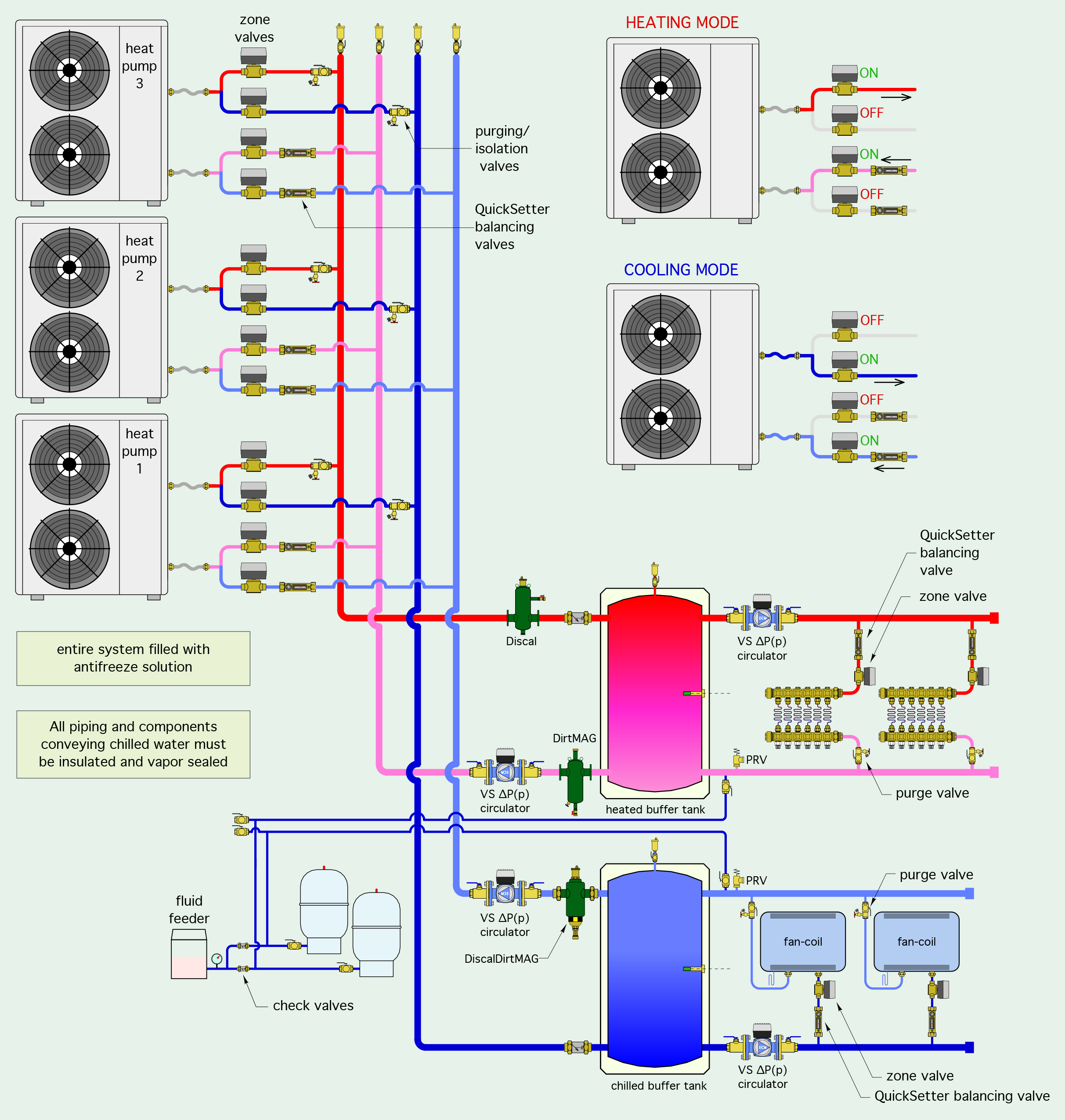
Heatspring Magazine 2 Pipe Versus 4 Pipe Buffer Tank Configurations
If the total piping.
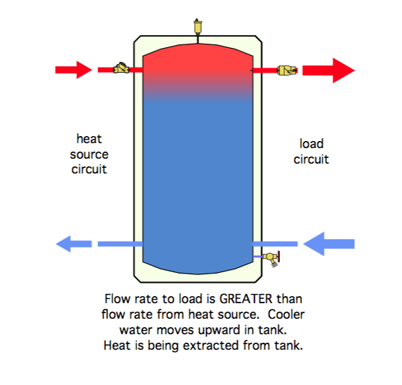
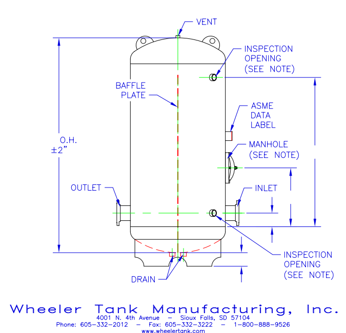
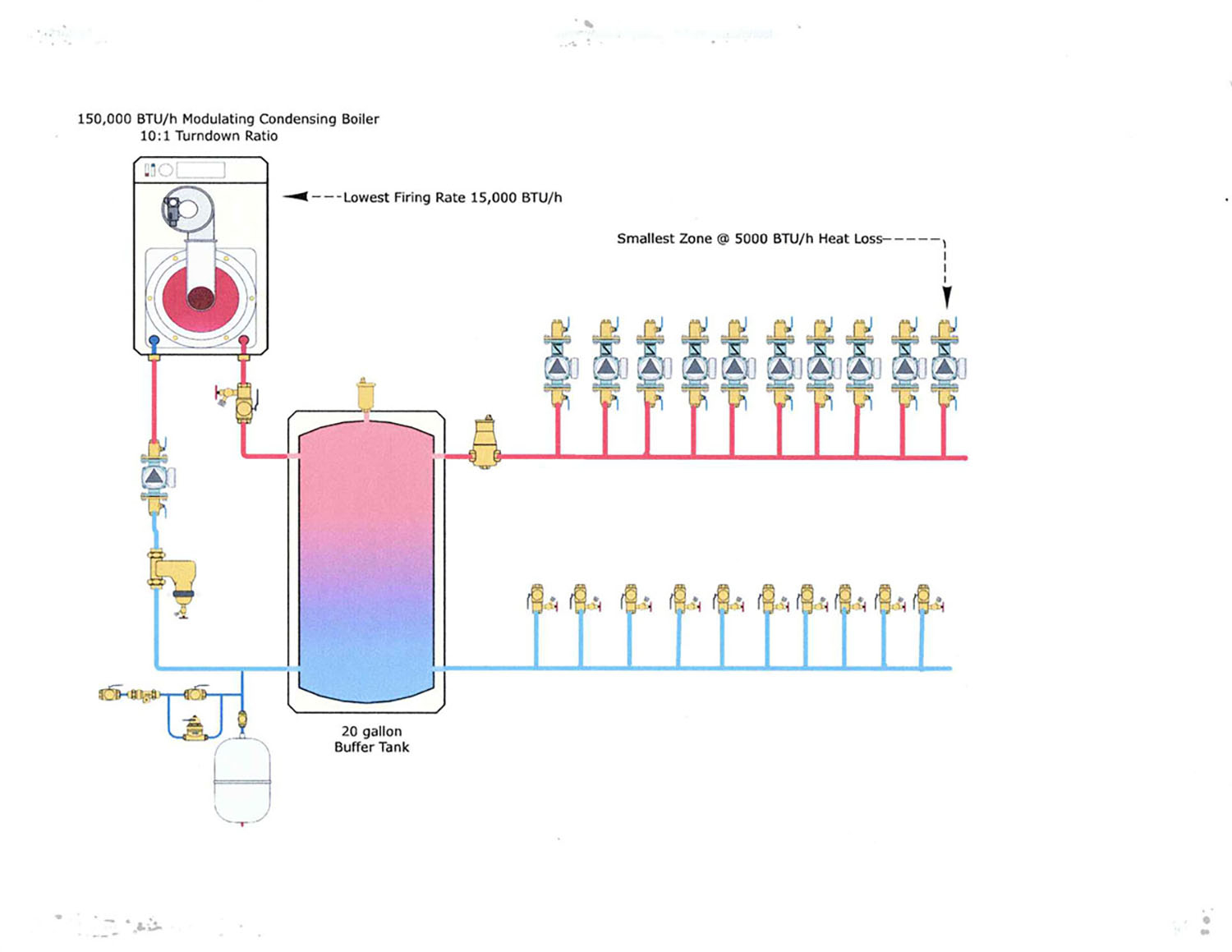
. As the system water enters the tank it is forced up and over the baffle before dropping back down. Computerized product selection helps you choose the Buffer Tank. The unit is designed with an internal baffle.
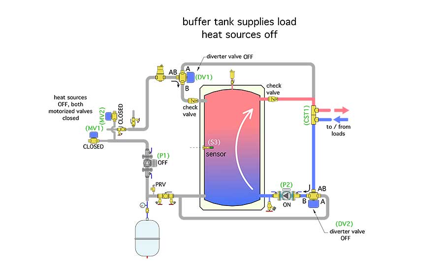
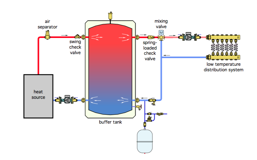
In this 2-pipe buffer tank scenario the flow velocity entering the buffer tank is lower than with the 4-pipe arrangement shown in figures 1 through 3. The water source used in the chiller may have a large number of impurities which will slowly accumulate in the bottom of the buffer tank through circulation. Check with Chiller Manufacturer for specific requirements.
Instantaneous SEH Semi-Instantaneous SSH. A 100 ton chiller requires 1000 gallons of system capacity for high accuracy control. BOX 55 CHESWICK PENNSYLVANIA 15024 Phone.
While 6 to 10 gallons are used for applications in which. SEH SSH SWH and USG. Chilled Water Buffer Tank Piping Diagram Plumbing And April 11th 2018 - Chilled Water Buffer Tank Piping Diagram here you are at our website At this time were delighted to declare we.
Piping diagram Model 1 Author. A deep dive into. Check with Chiller Manufacturer for specific requirements.
C h i l l e r C h i l l e r Chilled Buffer Tank B u f f e r T a n k AFD. It is not in the region of the costs. The chilled water from the chiller enters the cooling coil of the air handling unit AHU usually at about 67C 44F and leave at about 122C 55F.
How is the water circulated inside the tank. JMP Equipment Company 603 Diamond Hill Ct Greensboro NC 27406. Ad Templates Tools Symbols For Easy Piping Diagrams.
How is the water circulated inside the tank. Chilled Water Buffer Tanks CWB Series CEMLINE CORPORATION PO. A deep dive into the proper application of buffer tanks.
CEMLINE has made a series of typical piping arrangements for the Model Series. The AHU blows air through the cooling. Chilled Water Buffer Tank CWB Model.
Subtract that number from the chiller manufacturers recommended system capacity. John Siegenthaler offers 2 hours of insights into the proper application and piping of buffer tanks. Chilled Water Buffer Tank CWB Model.
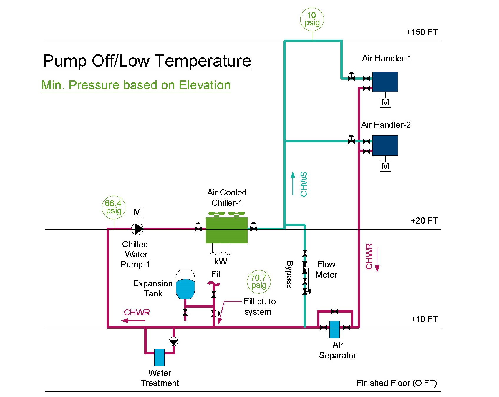
Expansion Tank Design Guide How To Size And Select An Expansion Tank For A Chilled Water System
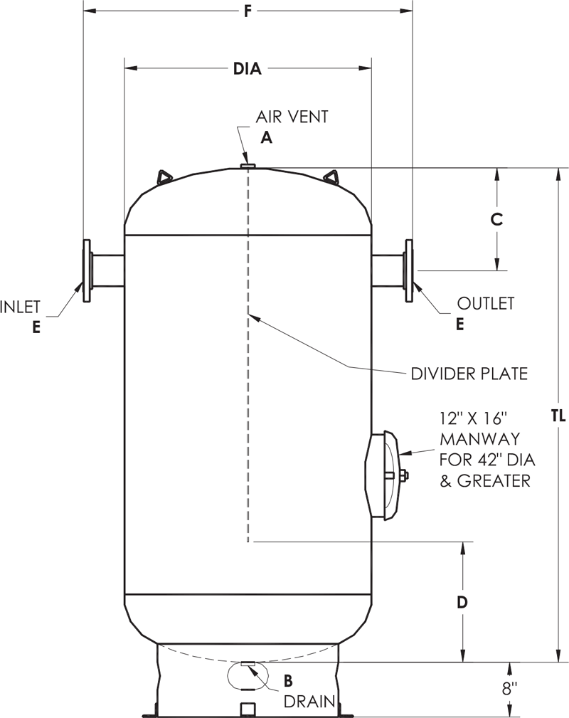
Asme Chilled Water Buffer Tanks Dimension Diagram Elbi Of America

Composite Pressurized Buffer Tank 120 Gallons
Details For Bypassing Thermal Storage 2017 10 24 Pm Engineer

All About Chilled Water Buffer Tanks American Wheatley
Chilled Water Buffer Tanks Wheeler Tank Manufacturing
5 Contemporary Sources For Chilled Water Caleffi Idronics

Buffer Tank 4 Pipe Vs 2 Pipe Heating Help The Wall
.jpg)
Chilled Water Hvac

The Finer Points Of Applying A 2 Pipe Buffer Tank 2017 04 28 Plumbing And Mechanical Plumbing Mechanical
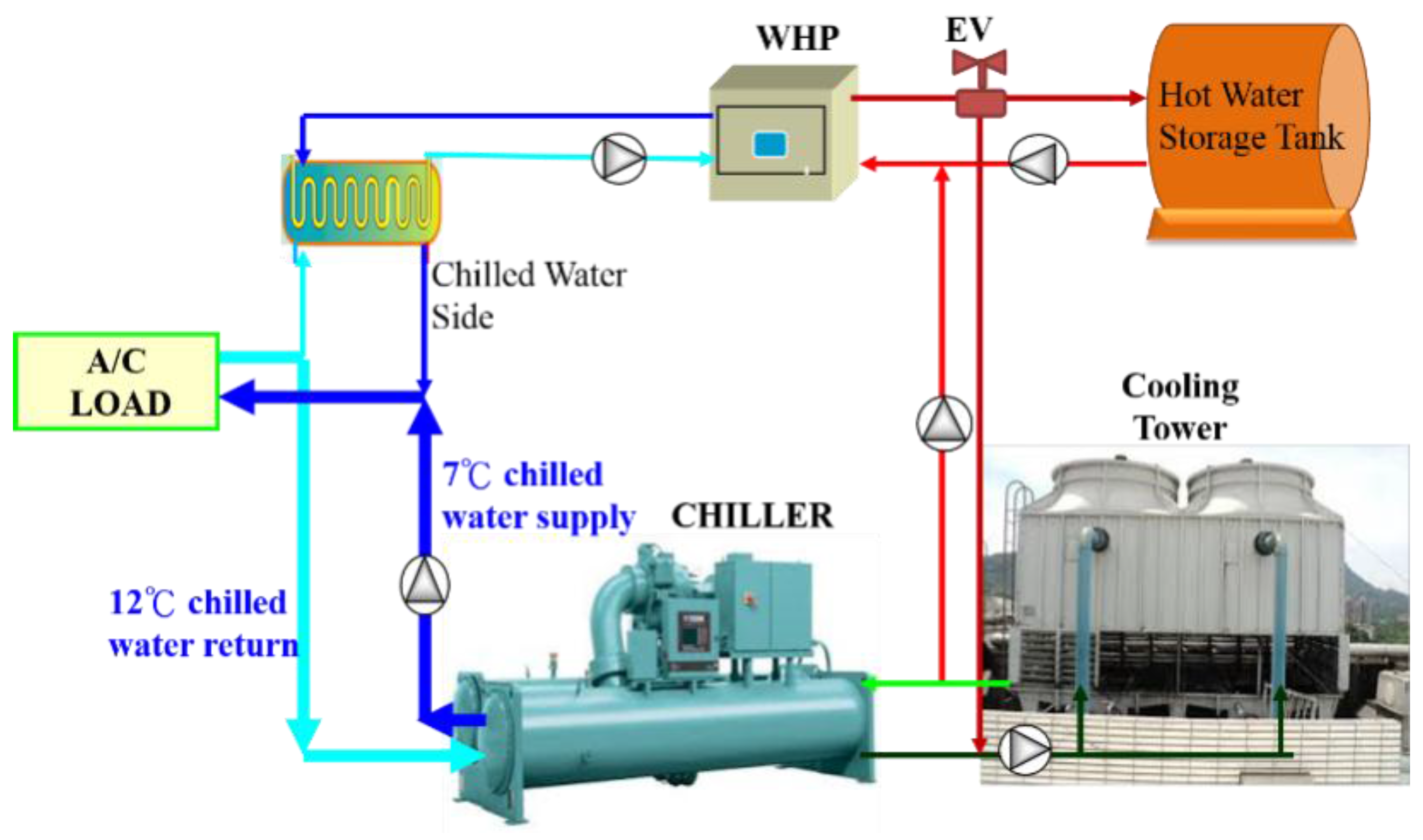
Sustainability Free Full Text Performance Analysis Of An Integrated Heat Pump With Air Conditioning System For The Existing Hospital Building Application Html
Shopping Boiler Buffer Tank Big Sale Off 69
Storage Tanks Energy Buffer Tanks
Heatspring Magazine 2 Pipe Versus 4 Pipe Buffer Tank Configurations

Bradford Chilled Water Buffer Tanks 7 21 10 Pdf Building Technology Heat Transfer

The Ultimate Guide To Industrial Chillers 2022 Amcon

Oil Buffer Tank Left Nitrogen Expansion Tank For Water Centre Download Scientific Diagram